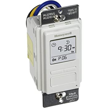
I recently purchased a Honewell Timer Switch from Amazon. The instructions that came with it for replacing an existing 3-Way switch don't work. Here is how to install it in place of an existing 3-way switch.
Working instructions
- The timer switch will replace one of the two existing light switches. The other switch will need to be re-wired.
- Turn off the circuit breaker and verify there is no power in the switch boxes.
- Identify which switch box is connected to the load (the lights) and which is connected to the hot (power).
a. Each switch box will have 2 black wires.
b. The black wire that comes from the same bundle as the red wire is a traveler.
c. The other black wire in each box will be either the hot or the load. Disconnect these wires from the existing switches, turn the power back on, and test which one is hot.
d. Turn the power back off when done with this step. - You don't have enough traveller wires to install the timer in the box with the power, so put it on the side with the load.
- Wire the timer:
a. Timer blue to load black
b. Timer white to bundle of white
c. Timer yellow to red traveler
d. Timer black to black traveler - Rewire the second switch.
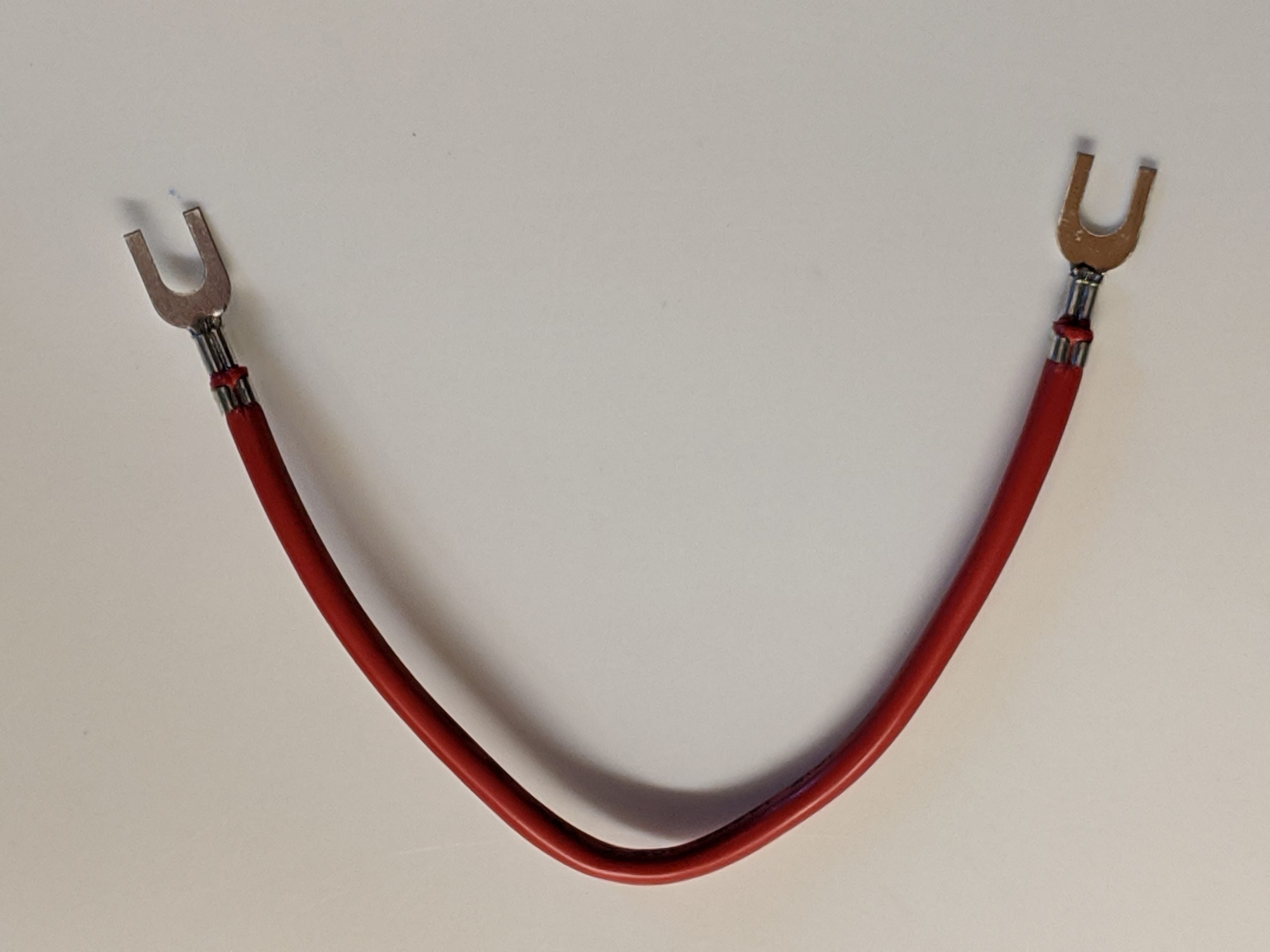
a. Disconnect the black traveler and connect it to the black hot wire. Either screw it under the same screw, or create a tail as illustrated below.
b. Make sure to use one black screw and one gold screw on the switch. Leave the second gold screw with nothing connected to it. It doesn't matter if the red gets connected to the black or gold screw as long as the black wires are connected to the other color.

Why this works
In a normal 3-way switch, the switch uses mechanical action to choose which of the two travelers (red and black) has power at any given time. The timer switch has an electronic relay (rather than something mechanical) to turn the power to the load on and off. It always needs power coming in on its black wire to power these electronics. It senses a change in state on its yellow wire and electronically switches the state of the blue load wire (light).
When this 3-way configuration is working properly, the remaining mechanical switch is not being used as a 3-way switch. You could replace it with a cheaper single-pole switch and reuse the 3-way switch elsewhere. For wiring purposes, a single-pole switch is missing the second, unused gold screw compared to a 3-way switch.
Honeywell's Instructions
The switch from Honeywell comes with a jumper wire.
The wiring diagram they provide shows it across two screws of the 3-way switch.
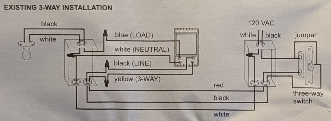
There is no way that is going to work. That is going to cause the 3-way switch to provide power to both the black and red travelers all the time.
You can instead convert the jumper into a tail. Cut one end off and strip it. Use it to connect the hot wires together with a wiring cap and put the other end on the 3-way switch as illustrated above.

16 thoughts on “Wiring a Honeywell 3-Way Timer Switch”
This helped me to install and troubleshoot a Honeywell timer for a three-way switch. The Honeywell instructions remove the function of the second switch while installing it this way keeps the second switch functional.
The way I think of it, the timer is a relay. When power is applied to or removed from the yellow wire, the relay changes state (open or closed). The second switch being wired to toggle power to the red traveler wire connected to the yellow timer wire allows the second switch to change the state of the relay.
Did you try wiring in accordance with Honeywell? I can see your logic in stating that installing the jumper will always leave that one traveler live. Although I do not have experience with this Honeywell timer, from your well thought out arguments I can see how Honeywell’s directions would actually work. It appears that the purpose of the jumper is to provide continuous power to the Honeywell electronic timer as you have stated. Also, as you have stated, the yellow wire on the Honeywell unit senses whether there is energy on the other traveler, which is the only information that the unit needs along with which switch position has been selected on the unit itself. From this information, the Honeywell unit will know whether or not to energize the light path in the same way as would happen with 2 properly wired 3 way switches.
I was unable to get it to work using the instructions provided by Honeywell and the jumper.
I’m exploring the addition of timer switches for the first time. My understanding is they typically allow for a program mode as well as manual mode, typically switching between the two by pressing the control cover which doubles as a switch. I’m surprised how or whether (or to what extent) full functionality remains at both ends. With 3 way wiring, can the 2nd switch turn the light ON regardless of whether the program switch is in auto or manual? Likewise, can the 2nd switch turn the light OFF, regardless of whether the program switch is in auto or manual? How does use of the 2nd switch interact with the auto mode? And if auto is interrupted, will auto resume on its own or does that require a visit to the primary switch?
When wired in the specific way I show above, both switches will work manually. If the light is on, pressing the button on either switch will turn it off. If the light is off, pressing the button on either switch will turn it on. Manual-mode and auto-mode work together pretty well, even from the second switch. Auto-mode resumes as expected, regardless of which switch was used manually.
Doing the same thing here and have a question hoping you can answer. What happens when the timer hits its “ON” time interval (and let’s say the light should stay on for an hour) but 5 seconds after the timer turned on the light, you turned off the light by flipping the manual switch (light is now off), now when the timer’s “ON” interval expires (an hour later), seems it should flip its internal switch and turn the light back on, right? Does this happen with your setup? I would hope that the timer has enough smarts to realize/sense the light is off and not try to flip its internal switch.
If the light is off and the schedule says to turn it off, it will stay off. The scheduler is smarter than just flipping the switch.
Would this set-up work if both switches were countdown timer switches?
We have two bath exhaust fans and two switches (one by shower and one on the opposite side of that wall inside the toilet closet). I want to run both fans at the same time with the option to control from either switch location utilize countdown timers so they turn-off after designated amount of time.
Your best bet would be to use one of the two switches and put a blank plate over the other. To make it work you would have to find a three-way countdown timer switch and I don’t know that such a thing exists. If it did exist it would have wiring instructions different than the instructions I posted here for this switch.
UPDATE: See my answer to the next question. I found a 3-way countdown timer that should work.
Will this work for the following application? Garage lights are left on and I want to have them time out lets say in 20 minutes and also be able to turn them on or off in house as well as the garage. There is an existing set of set of 3 way switches one in garage and the other in house. Load side is in garage. I want to be able to turn on light from in house as well as the timer if in garage. Or is there a timer that will work? Thanks to all.
The Honeywell switch is NOT a countdown timer, so it will not meet your needs. I use the Leviton LTB30-1LZ https://amzn.to/3g9vJMi in my bathroom as a countdown timer for the fan in a single pole application. The wiring instructions https://www.leviton.com/en/docs/Instruction_Sheet.pdf for it say that it can be used in 3-way setup as long as it is installed on the load side and used with a Vizia+® ON/OFF remote https://amzn.to/3psAbtQ for the other switch with a traveler wire between the two. The instructions say that the last used timer time is used with the remote switch since there aren’t separate buttons to choose how much time.
I thought what I had was a count down timer and like you stated it is not so there lies my issue of not getting it to operate in the manner I was after. Thank You so much for your insight and knowledge. I will try these and will respond with the outcome. Dave.
I installed a Honeywell FBA_36045 PLS750C1000 Timer today and I have a problem with the three switches. I wired black to black, blue to black, red and yellow together. There is no ground with the unit. I am getting power from the switch to the outside lights and the timer works great but when I use the other three way switch it cuts the power to the Honeywell timer. And the timer will only get power when I turn on the other three way switch. I need some assistance in getting both switches to work . Thanks.
It sounds like you need to rewire the other switch. The other switch needs to switch power to red, but no longer switch power to black. In a typical 3-way setup it switches both red and black. To work with the timer switch, it needs to be rewired.
Also struggling with the wiring of the Honeywell Timer. The wiring of the switches is accomplished thru a junction box between the two existing three way switches exactly like the attached diagram.
https://www.hometips.com/wp-content/uploads/2012/07/3-way-switch-wiring-diagram-1.png
Based on your comments, I need to put the timer on the switch on the right side of the diagram. But I am not sure. Any assistance would be appreciated.
I don’t see a way to get it to work with the load in the middle like that. It won’t work in the left switch because of the reasons I describe above. It won’t work in the right switch either. The timer switch requires 4 insulated wires. The right hand switch only has 3 insulated wires coming into it.